
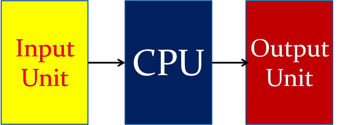
SIMPLE MODEL OF A COMPUTER
Computer is divided into three conceptual parts
- Input Unit
- Central Processing Unit (CPU)
- Output Unit
Figure shows the simple model of computer
 Loading...
Next Figure shows the organization of the basic input, processor, and output elements found in most computer systems. Let’s examine each system component in more detail.

INPUT UNIT
Input unit is that unit which provides a user interaction with CPU.
INPUT DEVICES : The devices through which the user communicate with computer known as input devices. Computer system uses many devices for input purposes. We have divided input devices into two categories
- Input devices, which allow direct human- machine communication. The keyboard of a workstation connected directly to a computer is an example of a direct input device. Other direct input devices- the mouse, input pen, touch screen, and microphone. All these devices are components used for interpretation and communication between people and computer systems
- Input devices, which require data to be recorded on an input medium, such as a magnetizeable material. Devices that read data recorded on specially coated, flexible plastic, or floppy disks, and magnetic tapes are often used.
The most commonly used Input devices are
The 80 Column Card : The 80 column card was one of the most widely used input device for early generation of computers. Today’s punched card is developed directly from an idea given by Herman Hollerith in 1889.The card has the following dimensions:
- Length -7 and 3/8 inches
- Width -3 and 1/4 inches
- Thickness -0.007 inches
The card is divided into 80 columns. The leftmost column is 1 and the rightmost column is 80. Only one character can be represented in each column. For the purpose of coding, the card is divided into 12 rows.
Type of Characters used
- Numeric characters – 0 to 9. Only one coulmn is punched to store one numeric character.
- Any alphabetic character is stored by punching two holes at one particular column i.e combination of both ZONE PUNCH and DIGIT PUNCH.
- Special characters-@,$,;,A etc.
Card Punching Machine : The card punching machine resembles an elaborate typewriter which punches a set of holes in a card instead of printing characters on a paper. The characters are converted into punched holes column. The different parts are as follows:
- Keyboard : it is identical with a typewriter keyboard having all the keys for numeric, alphabetic and special keys. When any character key is pressed, the corresponding code is punched in the column.
- Card hopper: it is a storage media for the blank cards and the cards come one by one for punching.
- Punching station: the card from the hopper comes to the punching station and set at column 1. After punching is over, the card moves to the next column and so on.
- Reading station : the punched card comes to the reading station where the information can be read as well as copied.
- Card stacker: the card stacker stores the punched card.
Card Reader: A card reader provides the interface between the punched card and the computer. The reader accepts the code and generates electronic pulses representing sequences of binary digit, which the computer can understand. The presence of a hole causes the light to create a pulse by triggering one of the cells. The speed of the card reader can vary up to 2000 cards/min.
Keyboard : One of the most important input device is Keyboard. When any of the keys is pressed, the keyboard transmits the information to the computer
The data can be entered directly into the computer through the keyboard. The special function keys help to reduce some of the otherwise necessary typing. One of the advantages is that one can input data as fast as you can.
Bar Code Reader : Bar Codes are particularly used by the retail trade for labeling goods. It is also used in Library Management System in numbering books, so the books issued or returned can be computerised.
Bar code reading is done by a light pen or scanner connected to a computer via a terminal device, also known as Bar Code Reader. The scanner or light pen is striked across the pattern of bars, a sequence of bits is generated and the information is recorded. From the thickness and spacing of bars, the computer recognizes the information and stores it for further processing.
Magnetic Ink Character Reader : Magnetic Ink Character Readers (MICR) are used mainly in banks as the input device. The system uses highly stylized character shapes printed in magnetic ink containing magnetizable particles. One MICR font known as E 13B, consists of the numerals 0-9 and four special characters. This is used for bank
cheques. The code numbers of the bank, the customer’s account number are all printed in magnetic ink. When a cheque is submitted to a bank, the amount of the transaction is inscribed on it, before the cheque is presented for computer processing. MICR systems uses character font mainly for machine recognition, so the characters have to be accurately formed. One advantage of MICR system is that the characters printed with ink containing magnetizable particles can still be read even when over stamped as in the case of bank cheques. MICR readers cannot verify, they can only identify. With a cheque, someone still has to verify the amount to be paid, to whom it is to be paid and most importantly, that the signature authorizing the payment is correct.
Speech Input : A speech input system accepts any speech. Every voice-input system or speech input system should be provided with a vocabulary. The words and phrases, which the system will recognise, are spoken with the system operating in a training mode where the particular patterns are created and stored.
The system is trained only to recognise the voices of one or more operators and a particular vocabulary for each operator. So unwanted or unauthorised speakers can
not use speech input. The speech are input to the computer either by the microphone, telephone or radio communication. A vocabulary ranges from 100 to 300 words. With the increase of vocabulary, the recognition power decreases. This is applicable in the situation where the operator needs to be free to move about a work area or to have his hands free or where an operator travels and relies on telephone contact with his work base.
Graphic Tablet : A graphic tablet is a flat surface which may be kept on a table. Most tables use an electrical sensing mechanism to measure the position of a stylus or a cursor placed on the tablet. In one method, a grid of fine wires is embedded below the tablet surface to carry a current.
When a stylus, which is like a pencil, is pressed down at a point on the tablet, a switch is closed and its tip is electro-magnetically coupled to the current-carrying grid wires. The strength of the picked up voltage indicates the (x, y) coordinates of the point. When the stylus is moved, the cursor on the CRT screen moves simultaneously to a corresponding position on the screen, to provide visual feedback.
For digitizing pictures, a lens-Iike cursor with a cross hair is used. This is positioned over the point to be digitized. The voltage picked up by a coil embedded in the cursor is used to estimate x and y coordinates.
Mouse : Today, in the era of GUI, every computer user uses a Mouse. A mouse is a small plastic box mounted on two metal wheels whose axes are at right angles. Each wheel of the mouse is connected to a shaft encoder which emits an electrical pulse for every incremental rotation of the wheel. The mouse is rolled around a flat surface. The flat surface need not have any embedded wires as in a tablet. As the mouse is rolled, its movement is sensed by the two wheels in two perpendicular directions. The distance moved is found by counting the pulses received from the shaft encoders. These are stored in registers. The values stored in the registers are sampled by the video controller 30 to 60 times a second. Visual feedback is provided by the cursor on the CRT screen which moves in synchronism with the mouse. Push buttons are mounted on top of the mouse and user can press them as he moves the mouse. The (x,y) coordinates of the mouse , when button is pressed, are stored by the computer.
Trackball : The trackball mechanically combines two variable registers in a single device, thus allowing the user to use one hand to enter both x and y information with a single device. The trackball is normally operated by rolling the ball with the palm of the hand.
Joystick : A joystick is a stick mounted on a spherical ball which moves in a socket. The stick can be moved left or right, forward or backward. It again makes use of two variable registers to specify x and y coordinates movement. Here the user pushes the handle to cause movement. The joystick may be designed with either of two basic methods. The first design consists of four switches, two for incremented & decrements the x axis and two for incremented & decrements the y axis. When this design is used, the joystick sends relative movement information. The second design makes use of variable registers and in principle works much like the trackball and mouse.
Touch Panel : Touch panel is a new locator device used mostly with Laptop computers which allows a user to point at the screen directly by moving his/her finger on the panel. Different technologies are used based on the resolution required. A medium resolution panel (100 resolvable positions in each of X and y directions) uses capacitive coupling. The touch panel is a glass coated with a conductor. Electronic circuits are used to detect the touch position from the change of the impedance across the conductive coating.
Light Pen : The light pen is a pointing device. If it is pointed at an item on the screen, it generates information from which the item can be identified by the program. However, the light pen does not generally have any associated tracking hardware. Instead tracking is performed by software, making use of the output function of the display.
The two main elements of a light pen are a photocell and an optical system which focussed onto it any light in its field of view. As shown in figure 1.3 the lens and photocell assembly is mounted in a pen shaped case which can be held in hand and pointed at any point on the CRT screen. The pen case has a finger operated switch which either opens or closes the electrical path from the photocell to the amplifier. The photocell output is amplified, shaped and fed to a flip-flop which is set whenever the pen is pointed at a sufficiently bright source of light. The state of this flip-flop can be read and cleared by the computer. When the flip-flop is set, it interrupts the computer and the contents of the X and Y registers are read to determine which item in the picture is currently being viewed by the light pen.
Other input devices are OCR(Optical Character Reader), Scanners, OMR(Optical Mark Reader) etc.
OUTPUT UNIT
Output Unit is that unit which provides a CPU interaction with user.
OUTPUT DEVICES: Like input units, output devices are instruments of interpretation and communication between computer and humans. These devices take machine- coded output results from the processor and convert them into a form that can be used by people (e.g. , printed or displayed reports) e.g. Visual Display Unit (VDU), Speaker, Printer etc…
We can categorize output devices in Soft Copy Output devices and Hard Copy output devices.
Soft copy Output devices are those only displays the output. E.g. Display Devices and memories like floppies, CDs & DVDs, Pen drive, Memory card etc.
Hard copy output devices are those which gives us output in printed form. Printers are the best example of output devices.
Visual Display Unit :A visual display device uses a cathode ray tube(CRT) to display information. It is also known as monitor. It is soft copy device. It looks like a television screen. VDUs are useful when the output is required within a short time. VDU is a type of terminal where the keyboard is used for feeding information and a screen for the display of both input and output. The monitor enables the user to have a visual check of the information before it is processed. The information is displayed silently and quickly on the screen than keyboard or printer. On screen anything will be displayed in 24 lines and 80 columns. It is a soft copy output device.
But to get hard copy of the output, the printing device is to be attached to the computer.
Printer : The printer is the output device by which we can gct the hardcopy of the output i.e. on the paper. It is hard copy device. We have various types of printers.
Dot Matrix Printer : The dot matrix printer is a serial printer which outputs one character at a time. The serial or character printer is much slower than a line printer and also cheaper. The print head of the dot matrix printer consists of a matrix of tiny needles, arranged in seven rows with nine needles in each, which print the character in the form of tiny dots. The speed of the dot matrix printer ranges from 80 to 360 characters per sec. (CPS). The quality of the print is not so impressive.
Line Printer : Line printer prints line by line. The rows of character sets are wrapped around a drum or attached to a chain. The drum or the chain revolves round the path of hammers, each of which corresponds to a print position. When the character to be printed is selected, a magnetically controlled hammer processes it onto an ink ribbon and hence onto paper like typewriter.
The stationery (paper) used on line printers is called continuous stationery(paper), though over varieties of paper can be used like bond paper, pre-printed electricity bills etc. Normally 132 characters or 136 characters are printed per line. The speed of the line printer varies from 300 to 2500 lines per minute.
Daisy Wheel Printer : Daisy Wheel printer is a special type of printer where it uses a daisy shaped disk made of metal or plastic that can hold 96 characters on its petals. The print heads are replacable so different character fonts can be used. The speed ranges from 25 to 60 CPS and prints 132 or 136 characters per line. lt is used with word processing systems where the quality of print is desired as the printing is of high quality.
Laser Printer : Laser Printers are letter quality printers. It is a non impact printer that creates, by means of a laser beam directed on a photosensitive surface, a latent image which is then made visible by a toner and transferred and fixed on paper.
Laser printers are very fast, produce very high quality print with different character fonts. Common laser printers print at the rate of 4 to 12 standard size pages per min.
CENTRAL PROCESSING UNIT (CPU)
CPU is the brain of computer, because all the operations (storing / processing/retrieval) are performed in this part.
CPU is divided into three main sections
- Memory
- Control Unit
- Arithmetic Logical Unit(ALU)
CENTRAL PROCESSING UNIT (CPU)
CPU is the brain of computer, because all the operations (storing / processing/retrieval) are performed in this part.
CPU is divided into three main sections
- Memory
- Control Unit
- Arithmetic Logical Unit(ALU)
MEMORY
A computer system also has storage areas, often referred to as memory. The memory can receive, hold, and deliver data when instructed to do so. Data that are being processed are held in primary memory (also called working memory or primary storage), which is capable of sending and receiving the data at very high speeds. Secondary memory (also called long-term memory or secondary storage), stores data not currently being used and operates more slowly, but it is capable of storing large volumes of data. This form of storage stores the data permanently in the given media and examples are floppy diskettes, magnetic tapes, magnetic drums, etc.
THE CONTROL UNIT
- How does the input device know when to feed data into storage?
- How does the arithmetic- logic section know what should be done with the data once they are received?
- How is the output device able to obtain finished rather than intermediate results?
By selecting, interpreting, and seeing to the execution of program instruction, the control section of the CPU maintains order and directs the operation of the entire system. Although the control section doesn’t process data, it acts as a central nervous system for the other data manipulating components of the computer. At the beginning of processing, the first program storage area. There it’s interpreted, and from there signals are sent to other components to execute the necessary action. Further program instructions are selected and executed, one after another, until the processing is completed.
A computer system also has storage areas, often referred to as memory. The memory can receive, hold, and deliver data when instructed to do so. Data that are being processed are held in primary memory (also called working memory or primary storage), which is capable of sending and receiving the data at very high speeds. Secondary memory (also called long-term memory or secondary storage), stores data not currently being used and operates more slowly, but it is capable of storing large volumes of data. This form of storage stores the data permanently in the given media and examples are floppy diskettes, magnetic tapes, magnetic drums, etc.
THE ARITHMETIC-LOGIC UNIT (ALU)
The arithmetic- logic and control sections together make up the central processing unit (CPU). All calculations are performed and all comparisons (decisions) are made in the arithmetic logic section of the CPU. Once data are fed into primary storage from input devices, they are held and transferred as needed to the arithmetic logic section where processing takes place. No processing occurs in primary storage. Intermediate results generated in the arithmetic logic unit are temporarily placed in a designated working storage area until needed at a later time. Data may thus move from primary storage to the arithmetic- logic unit and back again to storage many times before the processing is finished. Once completed, the final results are released to an output storage section and from there to an output device. The type and number of arithmetic and logic operations a computer can perform are determined by the engineering design of the CPU.
INPUT-OUTPUT INTERFACE(I/O Interface)
Input output interface provides a method for transferring information between internal storage and external I/O devices. Peripherals connected to a computer need special communication links for interfacing them with the central processing unit. The purpose of the communication links is to resolve the differences that exist between the CPU and each peripheral. The major differences are :
- Peripherals are electromechanical and electromagnetic devices and their manner of operation is different from the operation of the CPU and memory, which are electronic devices. Therefore, a conversion of signal values may be required.
- The data transfer rate of peripherals is usually slower than the transfer rate of CPU, and consequently, a synchronization mechanism may be needed.
- Data codes and formats in peripherals differ from the word format in the CPU and memory.
- The operating modes of peripherals different from each other and each must be controlled so as not to disturb the operation of other peripherals connected to the CPU.
To resolve these differences, computer system include special hardware components between the CPU and peripherals to supervise and synchronize all input and output transfers. These components are called interface units because they interface between the processor bus and the peripheral device. In addition, each device may have its own controller that supervises the operations of the particular mechanism in the peripheral.
Interface components are usually designed to operate with a particular microprocessor system bus with no additional logic besides address decoding. There are a variety of interface components in commercial use and each can be classified to be in one of four categories :
Parallel Peripheral Interface : A parallel peripheral interface
transfers data in parallel between the microprocessor and a peripheral device.
Serial Communication Interface : A serial communication interface converts parallel data from the microprocessor into serial data for transmission and converts incoming serial data into parallel data for reception by the microprocessor.
Special Dedicated Interface : A special dedicated interface is constructed to communicate with one particular I/O device, or can be programmed to operate with a particular device.
Direct memory Access (DMA) : A DMA interface is used for transferring data directly between an external device and memory. The bus buffers in the microprocessor are disabled and go into a high-impedance state during DMA transfer.
For Any Questions … Leave a Comment…
Thank you for various other good content. Wherever else may possibly everyone get that kind of information in these a great manner of composing? I’ve a speech in the future, and i am for the search for such information Opticals Asansol.
Could you tell me what theme are you utilizing on your internet site?
It looks great.
I located your site from Google and also I need to say it was a great find.
Thanks!
Your web site has excellent content. I bookmarked the site
Hi there! Such a nice post, thank you!